Greatest Common Divisor (GCD)

Greatest Common Divisor (GCD) |
 |
  while ( x != y ) {
    if ( x < y ) y = y - x;
    else x = x - y;
  }
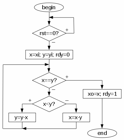
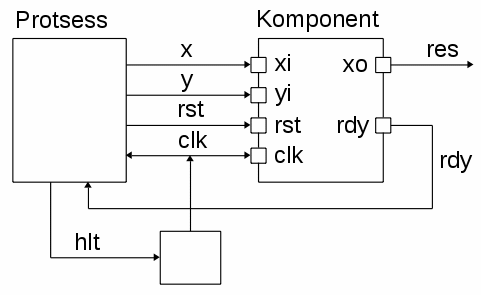
Input (x, y) and output signals (xo), and control signals (rst - reset, rdy - ready). The I/O protocol is based on the following - when rst=='0', inputs are latched into internal registers and rdy<='0' indicates that the algorithm has started. The test bench sets rst back to '1' and waits until rdy gets '1' - the algorithm has finished and the result is on the output. Of course, the polarity if control signals can be changed but the the test bench must be modified accordingly.
| Control Data Flow Graph | VHDL |
 |
library IEEE;
use IEEE.std_logic_1164.all;
use IEEE.std_logic_arith.all;

entity gcd is
  port (xi, yi : in unsigned(15 downto 0);
        rst    : in bit;
        xo     : out unsigned(15 downto 0);
        rdy    : out bit := '1';
        clk    : in bit);
end gcd;

library IEEE;
use IEEE.std_logic_1164.all;
use IEEE.std_logic_arith.all;

architecture experiments of gcd is
begin

  process
    variable x, y: unsigned(15 downto 0);
  begin
    -- Wait for the new input data
    wait on clk until clk='1' and rst='0';

    x := xi;    y := yi;    rdy <= '0';
    wait on clk until clk='1';

    -- Calculate
    while  x /= y  loop
      if  x < y  then y := y - x;
      else            x := x - y;    end if;
    end loop;

    -- Ready
    xo <= x;    rdy <= '1';
    wait on clk until clk='1';
  end process;

end experiments; |
Simulation results of the behavioral model (the test bench is below):

| Test bench | VHDL |
 |
library IEEE;
use IEEE.std_logic_1164.all;
use IEEE.std_logic_arith.all;

entity test is    end test;

architecture bench of test is
  signal clk, rst, rdy, hlt: bit := '1';
  signal x, y, res: unsigned(15 downto 0);

  component gcd
    port (xi, yi : in unsigned(15 downto 0);
          rst    : in bit;
          xo     : out unsigned(15 downto 0);
          rdy    : out bit;
          clk    : in bit);
  end component;
begin
  clk <= not clk after 10 ns when hlt='1';

  U1: gcd port map (x, y, rst, res, rdy, clk);

  process
    type int_array is array (0 to 7) of integer;
    constant a: int_array := (27, 33, 245, 121, 52, 333, 125, 422);
    constant b: int_array := (18, 256, 45, 11, 452, 121, 625, 312);
    -- expected results (GCD)  9,  1,  5,  11,  4,   1,  125,   2
  begin
    wait on clk until clk='0';
    for  i in a'range  loop
      x <= conv_unsigned(a(i),16);
      y <= conv_unsigned(b(i),16);
      rst <= '0';
      wait on clk until clk='0';
      rst <= '1';
      --wait on clk until clk='0';
      while  rdy = '0'  loop
        wait on clk until clk='0';
      end loop;
      wait on clk until clk='0';
    end loop;
    wait on clk until clk='0';
    hlt <= '0';    wait;
  end process;
end bench; |
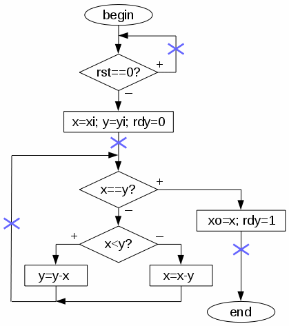
| Clocked behavioral model | VHDL |
 |
library IEEE;
use IEEE.std_logic_1164.all;
use IEEE.std_logic_arith.all;

architecture experiments of gcd is
  signal x, y: unsigned(15 downto 0);
begin

  process begin
    -- Wait for the new input data
    while  rst = '1'  loop
      wait on clk until clk='1';
    end loop;

    x <= xi;    y <= yi;    rdy <= '0';
    wait on clk until clk='1';

    -- Calculate
    while  x /= y  loop
      if  x < y  then y <= y - x;
      else            x <= x - y;    end if;
      wait on clk until clk='1';
    end loop;

    -- Ready
    xo <= x;    rdy <= '1';
    wait on clk until clk='1';
  end process;

end experiments; |
Simulation results of the clocked behavioral model:

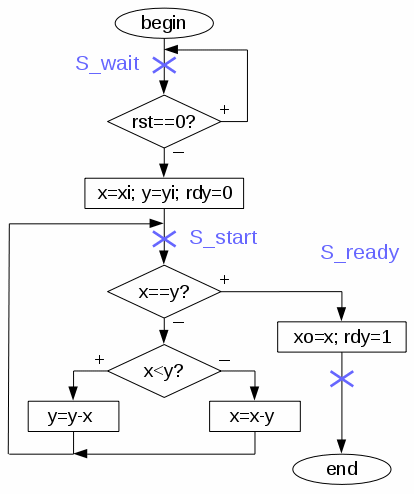
| Behavioral state machine | VHDL |
 |
library IEEE;
use IEEE.std_logic_1164.all;
use IEEE.std_logic_arith.all;

architecture experiments of gcd is
  type state_type is (S_wait, S_start, S_ready);
  signal state: state_type;
  signal x, y: unsigned(15 downto 0);
begin

  process begin
    wait on clk until clk='1';
    case state  is
    -- Wait for the new input data
    when S_wait =>
      if  rst='0'  then
        x <= xi;    y <= yi;    rdy <= '0';    state <= S_start;
      end if;
    -- Calculate
    when S_start =>
      if  x /= y  then
        if  x < y  then    y <= y - x;
        else               x <= x - y;    end if;
        state <= S_start;
      else
        xo <= x;    rdy <= '1';    state <= S_ready;
      end if;
    -- Ready
    when S_ready =>    state <= S_wait;
    end case;
  end process;

end experiments; |
Simulation results of the behavioral state machine model:

Beginning of the same simulation - changing of states is visible:

Hand-outs about the algorithm description and different implementations (2 slides per page).
The next five models fully match the register-transfer level (RTL) abstractions - there is a clear state machine and the data-part consists of components (register, multiplexers, subtracters, etc). Also, internal control signals exist. All models are synthesizable.
RTL #1 - single ALU, 3 clock cycles per iteration (see structure).
RTL #2 - single ALU, 2 clock cycles per iteration (see structure).
RTL #3 - comparator (less than) controls subtraction, 1 clock cycle per iteration – small but slow (sequential) data-part (see structure).
RTL #4 and RTL #5 - out-of-order execution – both subtractions are calculated first then the decision is made. The difference is how deciders/comparators are implemented (see structure #4 and structure #5).
Synthesis results and RTL schematics of different versions.
VHDL files to compare components - subtracter and two comparators, universal ALU, and test bench for checking.
SystemVerilog files of different GCD models - behavioral model, test bench, clocked behavioral model, behavioral state machine, RTL #1, RTL #2, RTL #3, RTL #4 and RTL #5.
SystemVerilog files to compare components - subtracter and two comparators, universal ALU, and test bench for checking.